A test case of the F-15 wing, aileron and flap was used to demonstrate the application of the Cobalt v7.0 Overset Module to moving control surfaces. In this type of application, the motion is prescribed and the limits of the grid motion are known ahead of time. There is also a very tight space between the control surfaces and the wing where the code must create a good hole-cut throughout the motion cycle. This geometry also presents the overlap of three grids at the intersection of the wing, aileron, and flap. All these qualities combine to present a realistic application to be able to simulate.
The total number of cells is this simulation is 31,947,245 – consisting of 27,664,464 cells for the wing grid, 2,310,120 cells for the flap grid, and 1,972,661 cells for the aileron grid. The wing is “mounted” to a symmetry boundary condition at the root chord of the wing. The gap between all surfaces is 0.15 inches. Two motions were simulated – (1) aileron oscillating and (2) flap deploy/aileron raised and return to original position.
The resulting hole-cut is shown on a cut-plane that cuts through the wing and aileron parallel to the chord for several aileron angles. The red grid is the aileron grid and the blue grid is the wing grid.
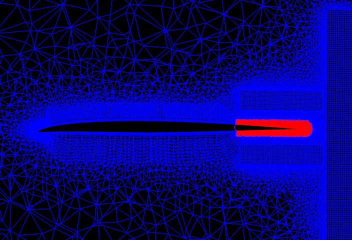
Aileron at Zero Deflection
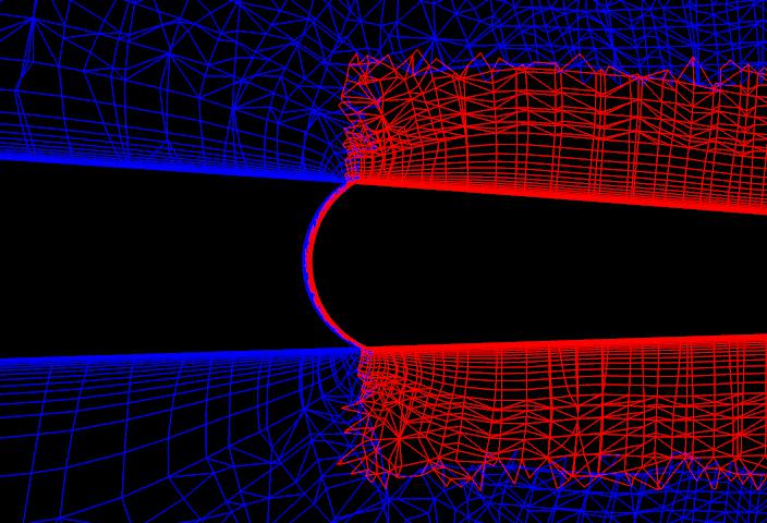
Aileron at Zero Deflection
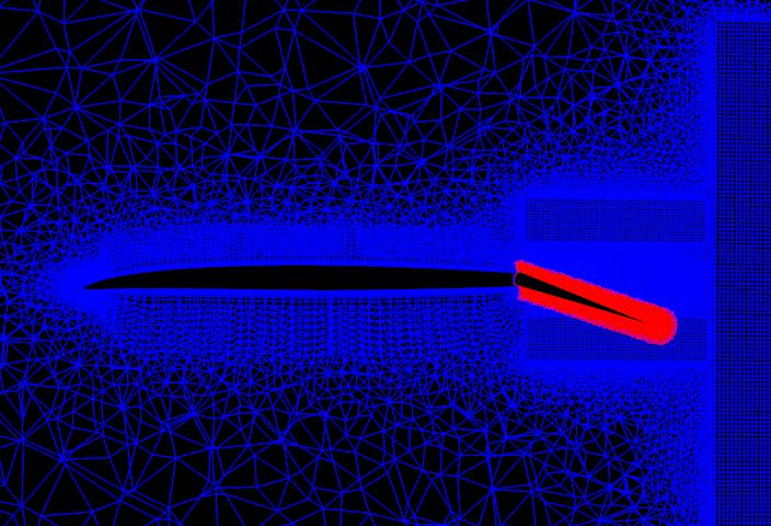
Aileron Deflected Downwards
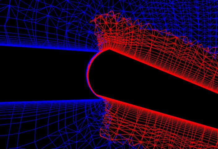
Aileron Deflected Downwards
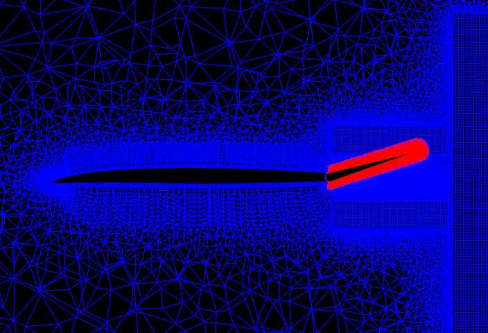
Aileron Deflected Upwards
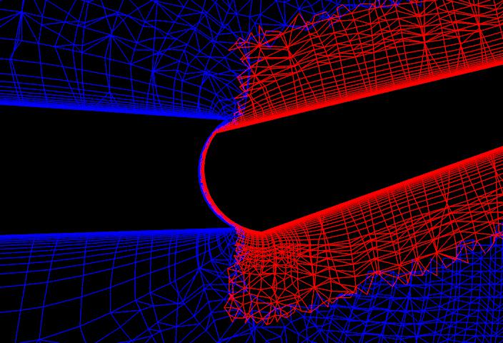
Aileron Deflected Upwards
The aileron oscillating case is shown below. The oscillation rate is 20Hz with a 20 degree amplitude. The first animation shows contours of pressure on the same cutplane as used in the images above. The following two animations show isosurfaecs of vorticity colored by pressure – one from an isometric view and one from a top view.
The flap-down/aileron-raised case is shown below. The flap deflects 31 degrees and returns to 0 degrees while the aileron raises to 15 degrees and returns to 0 degrees. These deflections are representative of control surfaces deflections.

